The limiting factor on the largest build-out in the history of computing is not silicon and it is not talent. It is interconnection queues, grid capacity and the price of a megawatt-hour. Models that should exist are deferred because the power to train and serve them is not available where and when it is needed.
A data centre is, structurally, an enormous roof and an enormous façade wrapped around a very large electrical load. Conventionally that envelope does nothing. It is the most valuable unused surface in the industry.
EnergyX does not supply a component into a data centre programme. It applies both engines — EnergyX Intelligence to evaluate thermal, power, generation, storage, manufacturability and economic options and verify a configuration; EnergyX Foundry to build the envelope that results — to the building, the plant and the dispatch strategy as a single engineering problem. Lifecycle services run beneath both.
01
Evaluates the envelope, on-site generation, storage, cooling and cost as one model; simulates the candidate configurations deterministically; verifies the one that meets the facility's engineering requirements before anything is fabricated.
Verified before build
02
Perovskite absorbers on a sub-micron active layer keep vertical and curved surfaces viable generation area; DFMA panels arrive as finished components so the envelope follows the architecture and fabrication stays off the critical path.
Materials · fabrication · envelope
03
Roof, façade and canopy replace cladding with generation. Power is produced at the point of the highest load density on the site, alongside — not instead of — grid supply.
Generation at the load
04
Generation, demand, storage state and grid price forecast ahead, then dispatched against the workloads the operator makes available for scheduling.
Operator-governed
05
Siting and irradiance modelling before the build; performance monitoring, certificate monetisation and grid-services participation after it. Metered results feed back into both engines.
Beneath both engines
Form follows the constraint that binds hardest — land, irradiance, planning envelope or proximity to load. The engines underneath do not change. Each scheme is a design concept; performance for a real site is established in a feasibility assessment, not read off a render.
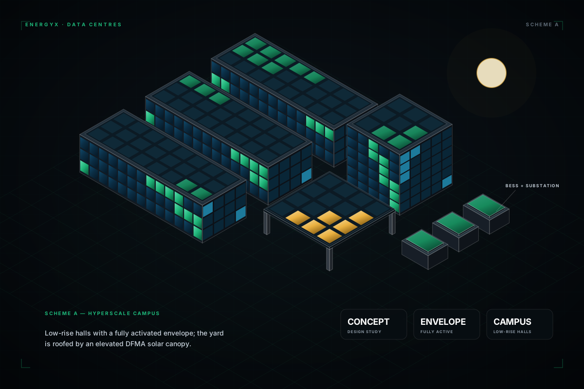
SCHEME A — CONCEPT
Low-rise halls with a fully activated envelope, and the service yard roofed by an elevated DFMA canopy so circulation space generates as well. Battery storage and substation sit inside the same optimisation loop.
SCHEME B — CONCEPT
A continuous double-curvature envelope, panelised by DFMA — the geometry a conventional flat module cannot follow. Capacity scales by adding arc segments, and the courtyard carries a ground array.
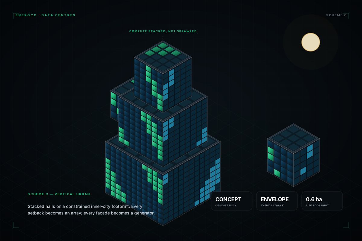
SCHEME C — CONCEPT
Halls stacked on a constrained inner-city footprint, close to the load they serve. Every setback becomes an array and every façade becomes a generator, which is the only way a dense site recovers meaningful surface.
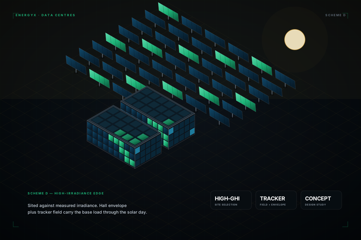
SCHEME D — CONCEPT
Sited against measured irradiance rather than assumed. The hall envelope and an adjacent tracker field together carry the base load through the solar day, with storage covering the shoulders.
Verified design and physical execution, on the same asset, change what the facility is: a load that also generates, forecasts and — where the operator chooses — trades.
A sub-micron, full-spectrum absorber performs on vertical and curved surfaces and in diffuse light, where conventional modules fall away. That is what turns a façade from a token gesture into real generation area.
Factory-laminated panels arrive as finished components. On a programme where every week of delay is deferred revenue, moving fabrication off the critical path is worth as much as the generation itself.
Power produced on the roof of the hall does not queue for interconnection and loses far less in transmission. It offsets demand at the meter, in the hour it is generated — reducing what the facility draws from the grid, not replacing the grid.
Before the build, Intelligence evaluates thermal, power, generation, storage, manufacturability and economic options and verifies a configuration against the facility's baseline. In operation, with a forward view of generation, demand and grid price, deferrable workloads — batch training, checkpointing, non-latency-critical inference — can be scheduled into the hours when on-site power is abundant, where the operator permits and the workload allows.
Predicted output is reconciled against metered output continuously, so degradation and underperformance surface as flagged assets. Efficiency certificates and grid services are monetised rather than left on the table.
Two metrics, kept apart. PUE measures total facility energy divided by IT energy; it is set by cooling and electrical design, climate, load and the measurement boundary, and on-site generation does not lower it. On-site generation is reported separately — annual energy coverage, distinct from peak output or daytime coverage — against a defined baseline. Both are established per project in a feasibility assessment, not shown as headline figures.
A feasibility assessment takes the site, IT load and utilisation profile, planning envelope and grid arrangements as inputs, and returns a verified envelope configuration, expected generation range with its assumptions, cooling and electrical design basis, and whole-facility economics.